Explain Kaplan Turbine
Main Characteristics of Kaplan Turbine
- Viktor Kaplan, an Austrian, developed this turbine in the year 1913.
- It is an axial flow turbine i.e. the falling of water on the runner or blades is along the axis. (See figure) and the water also exits from the runner axially.
- A Reaction type of turbine. This means that it utilizes the Kinetic Energy and Pressure Energy of the water.
- A low head turbine (10 m to 30 m).
- It requires a large quantity of water
- It has a high specific speed (600-1000)
- The vanes of this turbine are not fixed to the hub, it means the angles can be adjusted based on the requirement.
- Vanes number ranges from 4 to 8.
Also Read: Buoyancy and Floatation Concepts and Formulas Short Notes
Working Principle of Kaplan Turbine
Let us talk about the working principle of the Kaplan Turbine.
The working principle of the Kaplan Turbine is that it works on the principle-
- Axial Flow
- and Reaction
In axial flow the flow i.e. the water flow is parallel to the axis of rotation of the shaft or runner. And the reaction type means it utilizes the kinetic energy due to flow, as well as the pressure energy of the water for its operation.
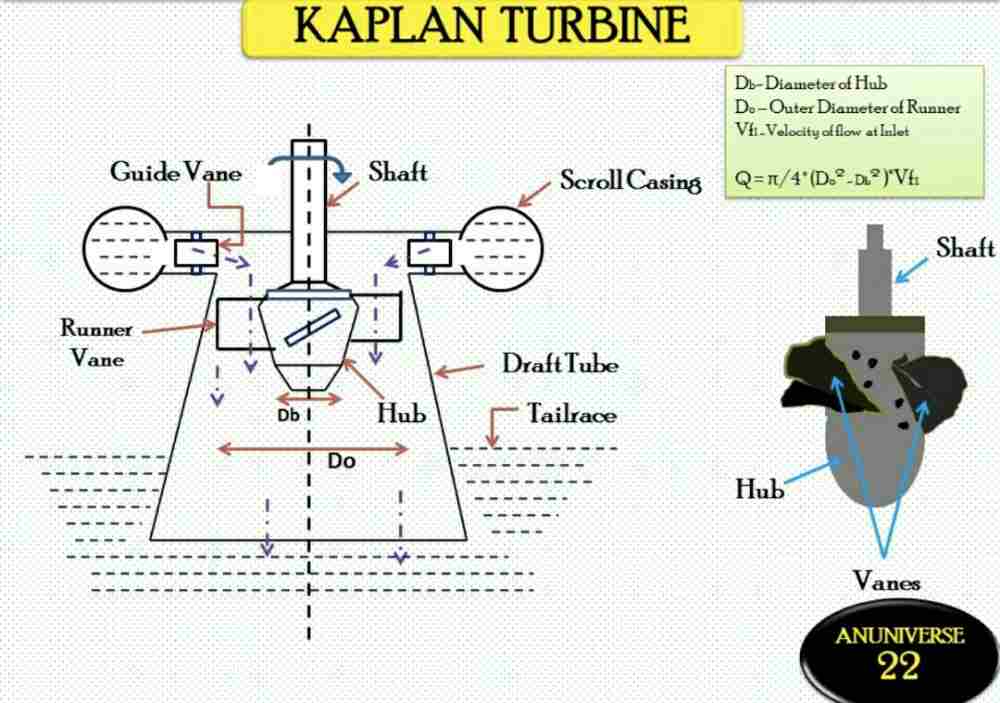
Kaplan Turbine Parts
As we can see in the above picture the main parts of the Kaplan Turbine are-
- Scroll Casing
- Guide Vanes
- Hub/Boss
- Adjustable Runners
- Draft Tube
Important Formulas of Kaplan Turbine
Here is the list of formulas that can be used to find or you can say to solve different types of numerical related to Kaplan Turbine.
\tan \alpha = \frac{V_{f_{1}}}{V_{w_{1}}} \tan \theta =\frac{V_{f_{1}}}{V_{w_{1}}-u_{1}} \tan \varnothing = \frac{V_{f_{2}}}{u_{2}}How does a Kaplan Turbine work
Lets us now talk about the working of Kaplan Turbine
- The water from the reservoir or via the penstock enters Scroll Casing.
- From Scroll Casing, the water through the guide vanes falls on the runner by turning 90 degrees and thus making it parallel to the runner (axial flow).
- After the waterfalls axially, the blades rotate due to the reaction force developed by the water.
- The water after falling on the blades and rotating the shaft is directed axially towards the draft tube (gradually increasing area). The pressure energy and the kinetic energy get decreased after coming out from the runner but the kinetic energy of the water is converted into the pressure energy (using a draft tube) thus increasing the pressure of the water.
Therefore in this way, the runner is rotated, and the shaft of the generator attached to the runner rotates and produces electricity.
What is the efficiency of a Kaplan Turbine?
The efficiency of Kaplan Turbine is very high. The efficiency is around 90%.
Efficiency Formula
Efficiency (ξ) = Work Done (WD) /(ρgQH)
Work Done per second (WD) = ρAV1 [Vw1 × u1]
What type of turbine is Kaplan Turbine
It is a reaction-type axial flow turbine.
The flow is axial along the axis of rotation of the turbine shaft or the hub. So, we can say a Kaplan Turbine is an axial flow reaction turbine.
Advantages of Kaplan Turbine
- Work at a low head efficiently
- The size of the turbine is smaller
- Construction of Turbine is easy
- The turbine requires less space
- The efficiency of the turbine is high compared to other turbines, up to 90%
Kaplan Turbine MCQ
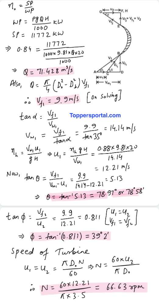
Question: A Kaplan Turbine working under a head of 20 meters develops 11772 kW shaft power. The outer diameter of the runner is 3.5 m and the diameter of the hub is 1.75 m. The guide blade angle at the extreme edges of the runner is 35 degrees. The hydraulic efficiency and the overall efficiency is 88% and 84% respectively. If the whirl velocity is zero at the outlet. Find the following
- Runner vane angles at inlet and outlet
- Speed of the turbine
A. 78.97º and 39º2′, 67 rpm
B. A. 68.97º and 35º2′, 56 rpm
C. A. 71.7º and 29º2′, 70 rpm
D. A. 81.97º and 89º2′, 51 rpm
Answer: Option A
Explanation:
Solution:
Given:
H = 20 m
Shaft Power (S.P) = 11772 kW
α = 35º
D_{o} = 3.5 m D_{b}= 1.75 m \eta _{h}= 0.88 \eta _{o}= 0.84 V_{w_{2}}= 0